The Travel option is
used to produce a TTMATRIX which may be envisaged as a table of
times and distances between all the points in your study. All
the DiPS planning programs which rely on this detailed
information access the latest TTMATRIX and thus it must be
completed before any planning runs are attempted. Road Speeds
and other relevant values can be defined using the Travel ,
Parameters menu option which reveals the Matrix Properties
notebook.
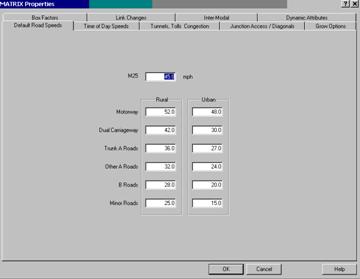
Default Road Speeds
Road databases are
stored in the roadfile, roadindx, and roadname files. For the UK these have a .UK file extension
and contain information on over 25,000 junctions and 75,000
links (down to street names, pedestrian areas, and one-way
systems for major urban areas). Each link has been allocated a
class based upon its type and where it is. There are two main
classes of rural or urban depending upon the location of the
link, but these may be additionally factored by use of Speed
Reduction Factors for specific cases such as congested urban
areas. The average road speed for each category of road may be
separately defined by the user. Any class of road or section of
road may be excluded by setting its speed to zero. The Default
settings have been developed over a number of years of
operational experience and have shown to produce industry
acceptable typical average speeds for HGVs. However speeds may
have to be modified for study data such as night running or the
use of smaller vehicles; and wherever companies have their own
agreed speed matrices.
To enable full
flexibility each class outlined below may be altered accordingly
:-
M25 - speed
class for all links of M25 motorway (all links are rural )
Other Motorways - all motorway
links apart from M25 (rural and urban)
Dual Carriageways - all road links
of more than 3 carriageways (whether or not a central
reservation is in place) for rural or urban areas
Trunk Roads - all Government
designated main trunk A roads (rural or urban)
Other A Roads - all other "A"
class roads (rural or urban)
B Roads - all roads with a "B"
classification (rural or urban)
Minor Roads - these have been
included where they constitute an important part of the
localised road network; for example in remote rural areas or in
urban areas (if they form an important access or recognised
through route)
The default road speeds are used to
define a standard set of speeds that apply to all vehicle
classes and at all times of the day or week.
Time of Day Speeds
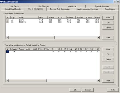
The Time of Day Road
Speeds option may be use to further refine road speeds to apply
different criteria
by time of day, day of week , country and vehicle class.
These parameters can
then reflect rush hours,
night running, or small non-HGV vehicle types for
example. Non Default Speed tables can be set and then applied to
days, vehicles and hours of the day.
Non Default Speed Tables
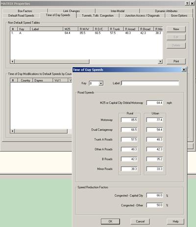
To define Non Default
Speed tables, click on the New button to display the input
screen for a link, type the appropriate values into the fields
provided and then click on the OK button.
A key value (A-Z) is used to apply the speeds to the
Modification Tables and a description can also be entered for
the Table (e.g. Rush Hour, Small Vans).
Values may be entered for standard speeds and Congestion
factors. Certain links on the road database were nominated as
either congested, mountainous or narrow as the database was
being established or updated. It is possible using the
percentages available to factor any type of link (A road,
B road or minor road etc.) that has a defined attribute of this
sort. The values actually reduce the speeds by the indicated
amount and NOT to that level. As an example on an urban B road
(normal defined speed = 18mph) going into
Uk capital city -
Central London
(speed reduction factor of 66%), the actual factored speed along
the link would be reduced to 6 mph. To clear an existing table
click on the relevant # no. and click on Delete. To change an
existing table select it by clicking on the required No. in #
column and modify the values before clicking on the OK button.
Modification
Tables
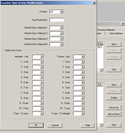
To define Modification
tables, click on the New button to display the input screen for
a link, type the appropriate values into the fields provided and
then click on the OK button.
Set the required country fro the list available. A blank
Day Restrictions field would indicate that the table applies all
week, with a seven digit number representing Sun-Sat employed to
stop it being used on certain days. Use 3 to disable the table
on a day (e.g. 3000003 would mean that the table applies Mon-Fri
only). In the case
of vehicles if the table applies to all vehicle leave the fields
blank. To restrict use to certain vehicle types, use the list
box to add any class previously set up using the Vehicle Class
option. The Explicit Vehicle Class Wildcard field represents a
method of ensuring a set of particular vehicle classes
only are used. The ??
wildcards can be used to include a variety of vehicle types – as
an example Vehicle Wildcard =
??TN would include vehicle classes of 11TN , 17TN or
21TN.
A key value
(A-Z) is then used to apply the speeds set for that table to the
each hour of the day as necessary. To employ default speeds
simply leave the field blank.
To clear an
existing table click on the relevant # no. and click on Delete.
To change an existing table select it by clicking on the
required No. in # column and modify the values before clicking
on the OK button. To re-sequence a table in the list, simply
select it and then click on the Move Up or Move Down button.
Using the Speed Tables in DiPS
The
Speed and Modification Tables are employed automatically
wherever necessary within the DiPS system to match the criteria
set. In terms of
priority of use, the first
matching Modification Table in the list is applied; that
is should a particular vehicle class (e.g. 17TN) be entered into a
number of different modification tables, the speeds employed
will be the first that match the necessary day and time. Hence
the priority of use may be influenced by sequencing the tables
using the Move Up or Move Down buttons.
To display
the speed tables used for a route, use the Style Heading =
Matrix on Style, Route Headings or see the Itinerary output.
Tunnels,
Tolls, Congestion
The
road database of the UK is stored in the roadfile.uk,
roadindx.uk, and roadname.uk files and contains information on
over 25,000 junctions and 70,000 links (down to street names,
pedestrian areas, and one-way systems for major urban areas).
Each link has been allocated a class based upon its type; the
basis of which is covered by the Road Speeds parameters.
However for special
cases classes such as ferries, tunnels and toll roads have been
established. To control use of these links use the speeds
parameter - set the speed to 0 to effectively ban that road
class if necessary. Values may be input for the following types
:-
Motorway Tunnels, Other
Tunnels (Toll and Free), Ferries - UK only, Toll Roads - UK
only, Projected Motorways - previously in use for M40, but since
opening is now in more widespread use for all major road
construction currently being undertaken.
Certain
links on the road database were nominated as either congested,
mountainous or narrow as the database was being established or
updated. It is possible using the
percentages available to factor any type of link (A road,
B road or minor road etc.) that has a defined attribute of this
sort. The values actually reduce the speeds by the indicated
amount and NOT to that level. As an example on an urban B road
(normal defined speed = 18mph) going into
Central London (speed reduction factor of 66%), the
actual factored speed along the link would be reduced to 6 mph.
The default settings have been developed over a number of years
of operational experience and have shown to produce industry
acceptable typical average speeds for HGVs in congested areas.
Junction Access / Diagonals
The
Grid Reference Sensitivity value in the Junction Access /
Diagonals section of Travel parameters is used to reduce the
accuracy of time and distance calculations between calls that
are close together. Set at the default value of 1 meter, all
calls with separate grid references will have a time and
distance between them stored on the TTMATRIX produced by the Run
Matrix process. If however the value is set to one of the higher
levels, the matrix calculation will assume that all calls within
that square are essentially in the same place and therefore
don’t require a separate time and distance row to be stored.
This saves both disk space and reduces the time taken to run the
matrix process. The higher the value is, the more calls will be
considered to be in the same place. This feature may prove
helpful when large studies are being undertaken, where accuracy
in the time/distance between calls is less important. The
sensitivity will also apply in the process of adding Extra Time
and Distance to Diagonals of the Matrix, where calls have the
same grid reference. Values for this function are set in this
section also.
Junction Access
parameter is used by the Window process as each unique grid
reference is attached to between one and four road junctions
(depending upon local geography). The object of the analysis is
to provide all the data and work files required to calculate
travel time and distances in the Matgen process. In order to
access the nearest a crowfly calculation is done and calibrated
using the following parameters :-
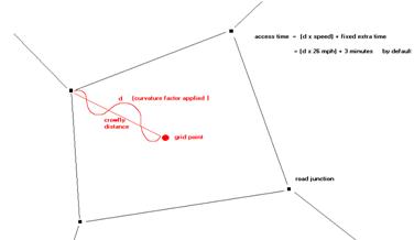
1. Curvature Factor
- this is used as a multiplier on the straight line distance
calculated using the Pythagoras Theorem from the grid point to
the junction. It is designed to add extra weighting to this
distance as it is often found that the access is not a straight
line and may involve the use of a number of small access roads.
2. Crowfly Speed
- this average speed is used to calculate the travel time
between the two points using the distance value from (1).
3. Fixed Extra Time
- this value is added onto the junction access time (from (2))
of the grid point by MATRIX as it is calculating time between
points or by the ITINARY program as it calculating journey
times. This value can also compensate for the
otherwise zero
inter-drop travel time between point with the same grid
reference; a factor which is also covered by use of the Extra
Values to be Added to Diagonal Elements of the TTMATRIX
parameter.
The default parameters
have been arrived at with considerable experience and would not
normally require alteration.
Maximum Acceptable Distance from a Junction -
As part of the Window process of attaching all unique grid
reference point to the nearest junctions, a list may be obtained
of all call points more than a certain distance away from the
nearest junction. This is a way of identifying data that may
have been entered incorrectly into KINGPIN. By default the value
is set to 2 miles (or kms if used) for all new studies. Increase
or decrease the value accordingly if required. It is usual for
the output list generated by the MATRIX program to appear in the
file MATRIX.OUT. View or print this file to see the data.
The Extra Values to be
Added to Diagonal Elements of the TTMATRIX parameters may be
used in the MATRIX generation to add extra time and distance to
locations with the same grid reference. This will prove useful
if the basic data to be used is not as accurate as could be
hoped. For example the data may give five drop points with the
same basic address input with which to locate them of
Birmingham
and no postcode information, and the points may be scattered
throughout the area. By adding extra time and distance between
these drop points it becomes possible to make any route plans
more realistic. These values will be added to any Junction
Access time and
distance calculated, and will appear on route output prints as
normal inter-drop data. When using this facility values must be
kept to reasonable levels to avoid problems that may occur in
the routing process. If values are too high the algorithm will
consider a detour to a neighbouring drop to be a better option
than doing another on the same grid reference as the comparative
detour time to the former is less.
Grow Options
Travel optimisation in
the MATRIX generation is performed using the Cost Factors. Using
the default settings of 1.000 for cost per minute, and 0.001 for
cost per mile will optimise for time, and produce the shortest
time routes from one location to another as minimising time is
considered much more important than minimising distance. The
reverse will give shortest distance routes. Any combination of
values for time and distance may be used to govern optimisation
as required.
Matrix Build Control
parameters may be used in conjunction with the Matgen Required
Number of Destinations value to reduce the time taken to
complete a MATRIX run. The time the Matgen process takes to
calculate the information (often termed "build a row") is a
direct function of the first grow limit if the required number
of destinations is reached within that time, or the second grow
limit if the first was not sufficient. This second grow will
treble the time needed. By default the required number of
destinations is set to 9999, with the first grow limit at 240
minutes and the second at 480 minutes. Almost without exception
the value of 9999 exceeds the number of matrix rows, so the
program will always build to the second grow limit as the first
will always be unsuccessful. However if the required number of
destinations is reduced, set the first grow limit such that the
majority of rows calculated reach the required number in the
first grow, thus avoiding the second grow and extra time. It
should be remembered that for most studies the default matgen
parameters will be quite sufficient as their size does not
warrant any changes in this area. As a guide only if there are
more than 1,000 unique references should any action be
considered.
Matrix Required Number
of Destinations parameter defines the amount of TTMATRIX stored
by the system for the current model or study. The default value
of 9999
means build a full matrix, that is calculate time and
distance values for every unique grid reference to every other.
Whilst this is acceptable for an average size study, of say 300
calls, in the case of 5,000 unique grid locations, as each cell
of the matrix requires 6 bytes of space, the hard disk space
required to store the information would be 6 x 5000 x 5000
= 150 Mb
(which is more than the average machine can hold). To
reduce the requirement, a lower value for the number of
destinations would mean a much smaller file (saving disk space
and program running time for the planning packages). For example
if a figure of 200 were used in the case above the new size of
TTMATRIX would be 6 x 200 x 5000
= 6Mb , with
data now only being stored for the nearest 200 locations to each
unique grid reference.
In using the vehicle
scheduling programs it is unlikely in most studies that a route
point would be linked to another that is more than 200 away from
being the closest (given the number of call points necessary to
provide 5,000 unique grid locations). However it may be
necessary in some cases to provide more tolerance for certain
data.
 The
MATRIX program will always store full rows of values from every
depot to every other grid reference in the window area, only the
inter-call times are affected by the destinations limit (the
TTMPART2 file). This means that the Print routines and Warefrom
module will work without any call to call data. Setting this
value to zero will also allow a matrix calculation to be done
using Postcode options. Therefore a fast matrix run for use with
these programs can be achieved by setting the Required Number of
Destinations field equal to ZERO before the matrix run. This
type of matrix will not be of any use for the route planning
programs as inter drop times would be required. This parameter
can also be used in conjunction with the Matgen Grow Limits
values to both reduce matrix size and run time. The time taken
to build a matrix is itself NOT a function of the required
number of destinations.
The
MATRIX program will always store full rows of values from every
depot to every other grid reference in the window area, only the
inter-call times are affected by the destinations limit (the
TTMPART2 file). This means that the Print routines and Warefrom
module will work without any call to call data. Setting this
value to zero will also allow a matrix calculation to be done
using Postcode options. Therefore a fast matrix run for use with
these programs can be achieved by setting the Required Number of
Destinations field equal to ZERO before the matrix run. This
type of matrix will not be of any use for the route planning
programs as inter drop times would be required. This parameter
can also be used in conjunction with the Matgen Grow Limits
values to both reduce matrix size and run time. The time taken
to build a matrix is itself NOT a function of the required
number of destinations.
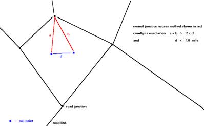
For call points that are
very close together geographically a crowfly calculation of
inter call time and distance information can be made rather than
the usual method of accessing the nearest road junction of the
network. This factor would be used in the routing operation.
Both the criteria set by
the ratio and distance must be satisfied before the system will
undertake such a process. By default the ratio setting is 2.00
and the distance is 1.0 mile; that is the distance taken
to access the nearest junction and return to the second
location must be twice the crowfly distance between the two
points, and this crowfly distance separating the two points must
be less than one mile.
Box
Factors
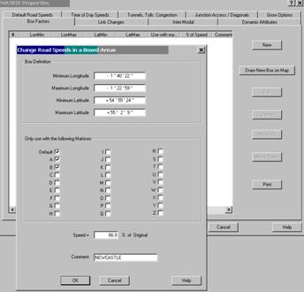
All road speeds in a
boxed area can be increased or decreased using the Speed Factors
facility. A factor of 120% will have the effect of increasing
all road speeds by 20%; factors less than 100% will have a
negating effect.
Box areas may be
established using mouse or Latitude and Longitude. Where two
boxes overlap the largest box number value will apply (i.e.
box
2 further down the list has priority over box 1).
Any areas not defined by
a boxed grid will use the default settings for road speeds. The
boxed area factor will have priority over default road settings
but not over any changes made to specific links using the
Individual Road Link Changes facility. A text description may
also be applied to each boxed area established using the field
provided.
Box Factors may be
applied to each Speed Table defined (Default and A-Z), allowing
further control on speeds in the defined area by time of day or
day of the week. Simply place a tick by each speed table
required.
To add box areas using the mouse to draw a rectangle , first draw a
pop-up window around the area in question on the graphics panel
using the LHB. Then after selecting Travel Parameters, Box
Factors, click on the Draw New Box on Map button.
To create a new Speed Box, click on the New
button to display the input screen for a box, type the
appropriate values into the fields provided and then click on
the OK button. To clear any existing values click on the
relevant # no. and click on Delete. To change an existing box
select it by clicking on the required No. in # column and modify
the values before clicking on the OK button. To move a Box,
simply select it and then click on the Move Up or Move Down
button. To send a copy of the settings to the default printer
use the Print button.
Link Changes
It is possible to
restrict the speed on any particular road section on the
roadfile database by using the Individual Road Link Changes to
modify the relevant base value set in either Road Speeds,
Special Classes of Road, or Road Speed Factors by Boxed Area
parameters. This facility is intended to cope with everyday
problems such as long-term roadworks, traffic queues, or toll
road links.
 Modify
Link Changes using Graphics Screen
Modify
Link Changes using Graphics Screen
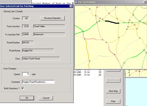
To add link changes
using the Highway Mode graphics screen to highlight links, first
draw a pop-up window around the area in question using the LHB.
Then after selecting Travel Parameters, Link Changes, click on
the New - Click Map button. The graphics window will then
re-draw displaying junction circles. To select a link, click on
the link required using the LHB and the dialog box will appear
as indicated. The dialog will display the link including
junction points and road information. Input the Changes as
required (set the speed = 0 to disable the link) and set the
both directions indicator. Click Ok to save changes or Cancel to choose another
link from the map if the current selection is not correct.
To clear any existing
values click on the relevant # no. and click on Delete. To
change an existing link select it by clicking on the required
No. in # column and modify the values before clicking on the OK
button. To move a link in the list, simply select it and then
click on the Move Up or Move Down button. To send a copy of the
settings to the default printer use the Print button.
Certain links will
appear in this section for every new study as part of the set-up
phase. These links include the Humber, Severn, Tamar and
Forth bridges and the Dartford Tunnel/Bridge. Speeds
for these will be set by default at 20 mph, and will over-ride
any constraints set in any of the sections discussed above.
It is useful to note
that any restriction place between two junctions will only apply
in that direction. For the restriction to be effective in both
directions two lines must be set up - one with the
A -> B
direction and the other with the
B -> A
direction.
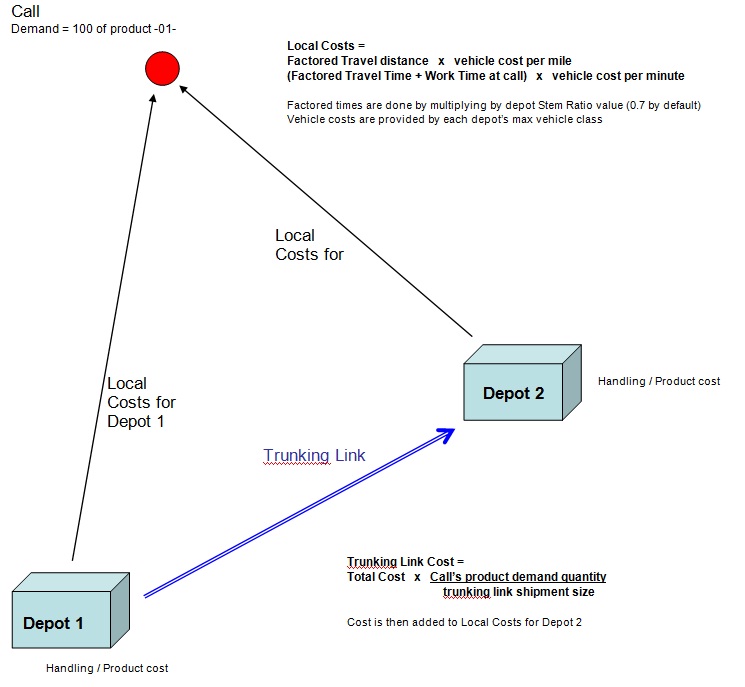
Running the WAREFROM
program will allocate calls to depots based upon a minimum costs
calculation. An
indication of the cost calculation is shown in the following
diagram. Key cost information must be set up before attempting
to run the routine. Minimum criteria are vehicle costs (either
cost per min, cost per mile, or both), so that Local Cost
calculations may be done.
Other more detailed
costs may be input into the model as required, using either
trunking links or product/handling costs at each depot. All
costs setup in the model are summed to produce an overall cost
per call, which is then divided by the total vehicle unit1 at
each call to provide a final cost per unit figure used to
allocate the call to its cheapest depot.
The Warefrom COST
screen may be regarded as the most important to check before
using Warefrom, as this screen defines the method and costs to
be used by the program in calculating Total Costs and in
performing any reallocation of calls between depot areas or
supply chains. The Maximum Number of Choices field must have a
valid number before the program is run (for normal studies 3
should suffice). The depot screen does contain two other items
of data used by Warefrom - the Stem Ratio and Stem Time fields.
The Depot Stem Ratio is applied to the times/distances for the
depot in question which are produced by Warefrom, giving results
which are closer to the more detailed Vanguard runs. Indeed, the
Stem Ratio may be obtain by running Vanguard, where it is given
as the ratio of total distance driven by all Vanguard routes to
the total of stem distances for all calls.
It is important to
remember that a depot with a Stem Ratio which is lower than that
of another depot will be at an advantage (other things being
equal) and will therefore be preferred in the allocation of
areas. For example, where a call is equidistant from the two
depots, say 100 miles, the depot with a ratio of 0.6 will be
preferred to the other with a ratio of 0.7. The relative costs
(at 1p per mile) would be 60p and 70p. The main function of the
Stem Ratio is to take inter-drop travel into account within
Warefrom - the program otherwise produces results based solely
on Stem time/distance.
In its simplest form
the Local Costs are summed –
Local Costs =
Factored Travel distance x
vehicle cost per mile
+
(Factored Travel Time +
Work Time at call)
x vehicle cost
per minute
Factored times are done by multiplying by depot Stem Ratio value
(0.7 by default)
Vehicle costs are provided by each depot’s max vehicle class
When
Trunking Links and Handling / Product costs are added, the
following items are also summed as a trunking cost and then
added into the total cost –
Trunking
Link Cost
Total Cost
x
Call’s product demand quantity
Trunking link shipment size
Handling
Costs
+
Handling Cost at depot x
product
demand quantity
Product Costs
+
Product Cost at depot x
product
demand quantity
An
in-depth listing of the calculated costs for calls and supply
chain numbers may be obtained by setting the Detailed Call Costs
Report. These more detailed cost reports may be achieved for ALL
calls (by default = ALL) or a single call ident number, input in
the field provided. The format gives a section for each call
location with a separate line for each delivery depot and supply
chain loaded into the run, so that comparative costs may be
examined. The ident with address information is provided along
with the vehicle class providing the cost information. This
vehicle type is obtained from the Maximum Vehicle field of the
Call, being the largest vehicle that may access the call. If any
particular vehicle type is not available at a delivery depot,
this supply chain option will not be considered for the call and
a warning message will be displayed accordingly. The TOTAL COST
calculation is the sum of all the constituent parts in use and
the call is allocated initially to the cheapest supply chain
option.
Calls that are outside
of the Depot Stem Time limit will not have calculated costs and
will be marked with a TOO FAR AWAY or REQUIRED ROUTE LENGTH >
MAX message. Any Carriage Paid calls allocate to the nearest
cheapest depot (the appropriate Stem Driving times from each
delivery depot location are displayed) with the Vehicle Class
set to 3rd to nominate a third party distribution function.
Explicitly allocated calls are marked with an
e and costs
not calculated from all supply chains since that call cannot be
considered for re-allocation.
Calls
that do not meet any valid depot criteria are marked with a
DEFERRED - NO DEPOT CHOICES warning message, as in the example
below with no possible vehicle choices to meet access
restrictions. Cost per Unit (Vehicle Unit 1) are calculated to
show the relative cost differences from each chain taking into
account the product demand volumes. It is this figure that is
compared if the call requires allocation to its second or third
choice supply chain with the first choices being over-allocated.
2)
Costs From Each Supply Chain
Supply
TOTAL Trunk
----- Local Costs ----------
Ident Name
Depot Chain
COST
Cost
Veh
Fixed Time
Dist
C102
LEEDS
A 1
43
0
7.5T
0
41
2 Cost/Unit=
21.50000
B
2
58
27
7.5T
0
25
6 Cost/Unit=
29.00000
C
3
75
21
7.5T
0
40
14 Cost/Unit=
37.50000
D
4
613
510
7T-4
0
80
23 Cost/Unit=
306.50000
Other
Parameters in Warefrom
The
Depot Stem Time limits the extent to which depot areas may be
grown. Calls which are further than this limit from the depot in
question cannot be allocated to that depot's area. A common use
of this parameter is to ensure that areas can be served by
specific one-day or two-day routes. By limiting the area to the
equivalent of half of a shift's driving time, calls would not be
allocated where deliveries would require a second day out. The
possible service levels for specific calls can be investigated
in Vanguard/Egotrip. Any vehicle class or class wildcard
specified in a Call Banned Vehicle parameter will also prevent
that call being allocated to a distribution Depot with that
class (or matching for wildcards) set as its Maximum Vehicle.
For example a call with a banned vehicle of
A??? would
not be allocate to a depot with a maximum set to AR22 or ARIG.
If a call cannot be allocated to a depot for this reason the
message
BANNED VEHICLE CLASS (Wrong Type of Supplier)
will appear in the Detailed Call Costs output section.